
 Code 3 Lead
 Code 4 Lead
 Code 5 Lead
 Code 6 Lead






Correct Lead Bay Sizes Explained (Code 4–8) | Architect CPD Guide


Correct Lead Bay Sizes (Code 4–8) — The Definitive Bay Sizing Guide for Rolled Lead Sheet
If you want long-life performance from lead sheet roofing, the non-negotiable starting point is correct lead bay sizes. Most defects attributed to “lead failure” are actually incorrect lead bay sizes: bays laid out beyond dimensional guidance, movement constrained by joint detailing, or bay geometry set for appearance rather than thermal behaviour. This guide explains correct lead bay sizes for Code 4, Code 5, Code 6, Code 7 and Code 8 rolled lead sheet, using the same terminology that specifiers, surveyors and competent installers use on site.
It is written for architects, specifiers, contract administrators and surveyors who need a clear reference for correct lead bay sizes, including a distinction between bay length (in the direction of fall) and bay width (across the fall). If you are coordinating leadwork to drawings, schedules or NBS clauses, treat this as CPD-grade guidance that supports buildable, maintainable lead roofs.
For leadwork workmanship expectations and good practice, also see Leadwork Standards. For specialist delivery on heritage and high-risk junctions, reference Neal Roofing leadwork services and specialist support from The Lead Lads. For practical demonstrations of detailing, laps, drips and rolls, the Lead Lads YouTube channel is a useful visual companion for designers and trainees.
Why Correct Lead Bay Sizes Matter
Lead moves. It expands and contracts significantly with seasonal temperature change and solar loading. If bay geometry exceeds recommended limits, the lead attempts to move but cannot do so without concentrating stress. Over time, that stress causes predictable mechanisms of failure, including:
- fatigue cracking across bays (often at mid-span or near restraint points)
- rippling and buckling that traps debris and encourages standing water
- uplift and deformation between rolls in storm exposure
- tearing at fixings where joints restrain movement
Specifying heavier lead is not a remedy for oversized bays. It may change the mode and timing of failure, but it does not remove movement. The route to durability is correct lead bay sizes paired with restraint-free detailing.
Design Principle (CPD)
Bay sizing is a primary design control. It must be set at concept and developed design stage, coordinated with roof falls, outlets, step/drip positions, structure, insulation sequencing and safe maintenance access. Correct lead bay sizes cannot be “fixed on site” without altering joint layout.
Critical Definitions (Avoid the Common Design Error)
Before using the tables, fix the language. Most specification disputes on leadwork start with confusion between bay width and bay length. Correct lead bay sizes depend on controlling both dimensions independently:
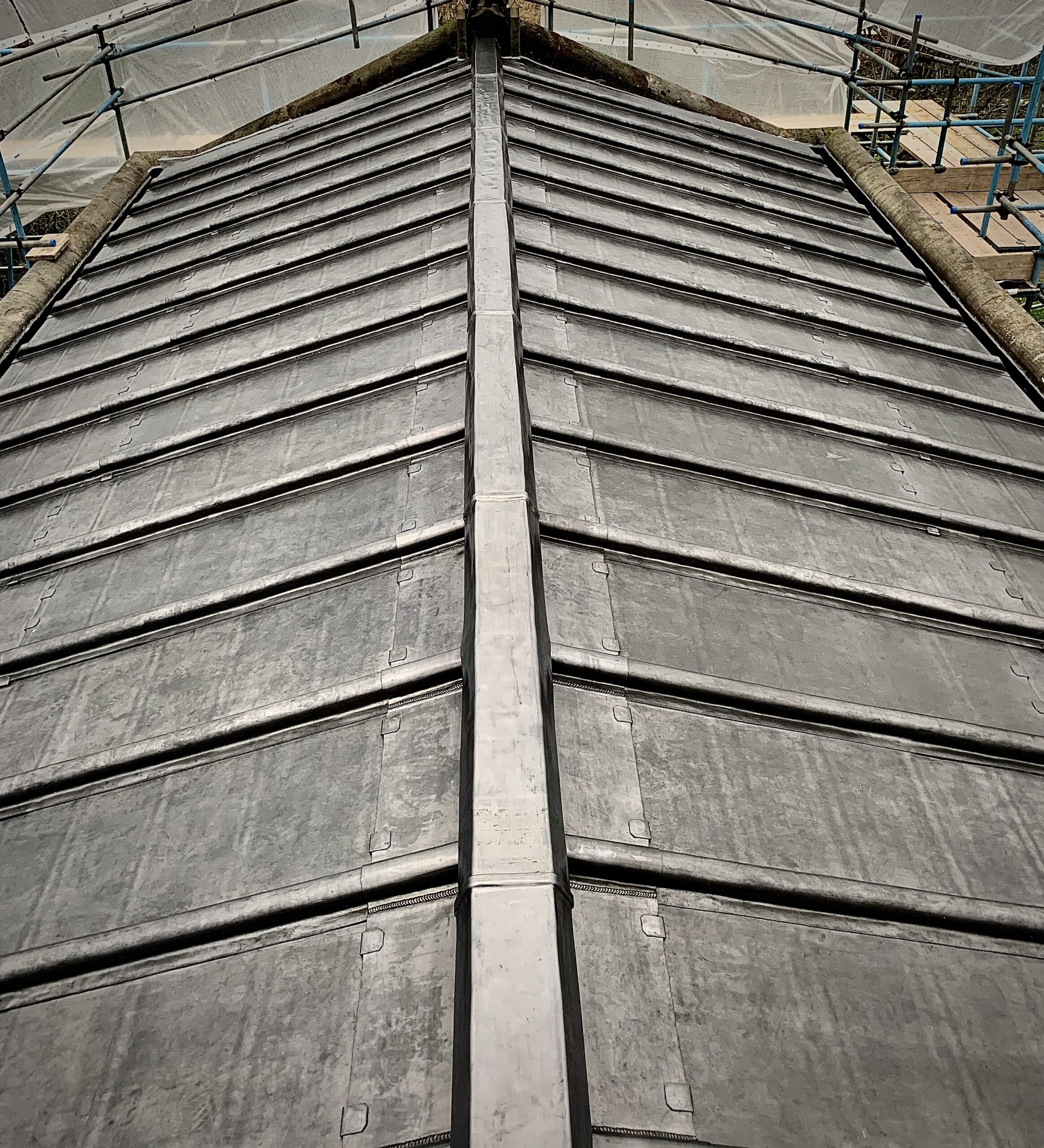
- Bay length = the dimension in the direction of fall (controlled by drips on flat roofs, and laps on pitched roofs)
- Bay width = the dimension across the fall (controlled by rolls or mechanical joints)
If either bay length or bay width exceeds guidance, the bay is oversized — even if the other dimension is within limits. In other words, correct lead bay sizes are achieved only when both the bay length and bay width comply.

Maximum Bay Sizes for Flat & Low-Pitched Lead Roofs (≤10°)
For flat and low-pitched roofs, bay length in the direction of fall is controlled using drips (steps). Bay width across the fall is controlled using rolls or mechanical joints. The following table sets out correct lead bay sizes as maximum dimensions for Code 4–8 lead sheet on roofs up to and including 10° pitch:
| Lead Code | Max Width Between Rolls / Mechanical Joints (mm) | Max Length Between Drips (mm) | Design Notes (Specifiers) |
|---|---|---|---|
| Code 4 | 500 | 1500 | Use where geometry is tight or detailing is complex. Keep bays conservative in exposure. |
| Code 5 | 600 | 2000 | Common for smaller flat roofs. Ensure drips are placed to control length. |
| Code 6 | 675 | 2250 | Most frequently mis-sized. Coordinate roll set-out and drip spacing early. |
| Code 7 | 675 | 2500 | Length increases, width does not. Do not assume “thicker = wider bay”. |
| Code 8 | 750 | 3000 | Typically reserved for high-wear areas or demanding exposure. Still requires compliant bays. |
Important: These are maximum dimensions used to define correct lead bay sizes. In exposed sites, high-solar orientations, parapet gutters, or roofs subject to foot traffic, bay sizes should be reduced below maxima for robustness.

Maximum Bay Sizes for Pitched Lead Roofs (11°–60°)
On pitched roofs, bay width is still controlled by joints/rolls across the fall, but bay length is controlled by laps (not drips). The following table summarises correct lead bay sizes for pitched roofs between 11° and 60°:
| Lead Code | Max Width Between Joints (mm) | Max Length Between Laps (mm) | Design Notes (Specifiers) |
|---|---|---|---|
| Code 4 | 500 | 1500 | Conservative bay sizes; useful where junction density is high. |
| Code 5 | 600 | 2000 | Typical for smaller pitched details; ensure laps are buildable. |
| Code 6 | 675 | 2250 | Often appropriate for pitched panels; verify restraint-free laps at abutments. |
| Code 7 | 675 | 2400 | Length increases modestly; do not exceed without redesign. |
| Code 8 | 750 | 2500 | High-demand use; still subject to movement limits. |
Maximum Bay Sizes for Steeper Pitched Roofs (Above 60° and up to 80°)
For pitches above 60° and up to 80°, bay sizing remains movement-governed. The lap-controlled bay lengths align with the following limits, which should be treated as correct lead bay sizes for steeply pitched applications:
| Lead Code | Max Width Between Joints (mm) | Max Length Between Laps (mm) | Design Notes (Specifiers) |
|---|---|---|---|
| Code 4 | 500 | 1500 | Use for small-format steep details, dormer cheeks, and tight geometry. |
| Code 5 | 600 | 2000 | Coordinate fixings and laps carefully to avoid restraint. |
| Code 6 | 675 | 2250 | Appropriate for many steep applications; detail laps for drainage and movement. |
| Code 7 | 675 | 2250 | Note reduced lap length vs 11°–60° range; do not assume longer is permissible. |
| Code 8 | 750 | 2250 | High demand but movement limited; pay attention to restraint at perimeters. |
Bay Width Control: Rolls and Mechanical Joints
Bay width is the across-fall dimension between rolls or mechanical joints. Rolls provide a controlled “movement zone” and help resist uplift. When bay width exceeds limits, the sheet becomes prone to uplift and deformation during wind events, especially where insulation upgrades and airtightness changes have altered internal pressure regimes.
To achieve correct lead bay sizes across the fall:
- Set out roll centres early and coordinate with outlets, upstands and penetrations.
- Avoid “visual module” layouts that exceed width guidance.
- Do not increase bay width simply because bay length has been reduced.

Bay Length Control: Drips (Flat Roofs) and Laps (Pitched Roofs)
Bay length is the along-fall dimension controlled by drips or laps. Designers sometimes attempt to reduce joint count by running longer bays to simplify appearance. This almost always produces non-compliant geometry and drives future defect risk.
To achieve correct lead bay sizes in the direction of fall:
- On flat roofs, introduce drips at the maximum spacing (or closer in exposure).
- On pitched roofs, ensure lap positions remain buildable and do not create trapped water zones.
- Coordinate fall direction and outlet position so drip and lap set-out makes sense.
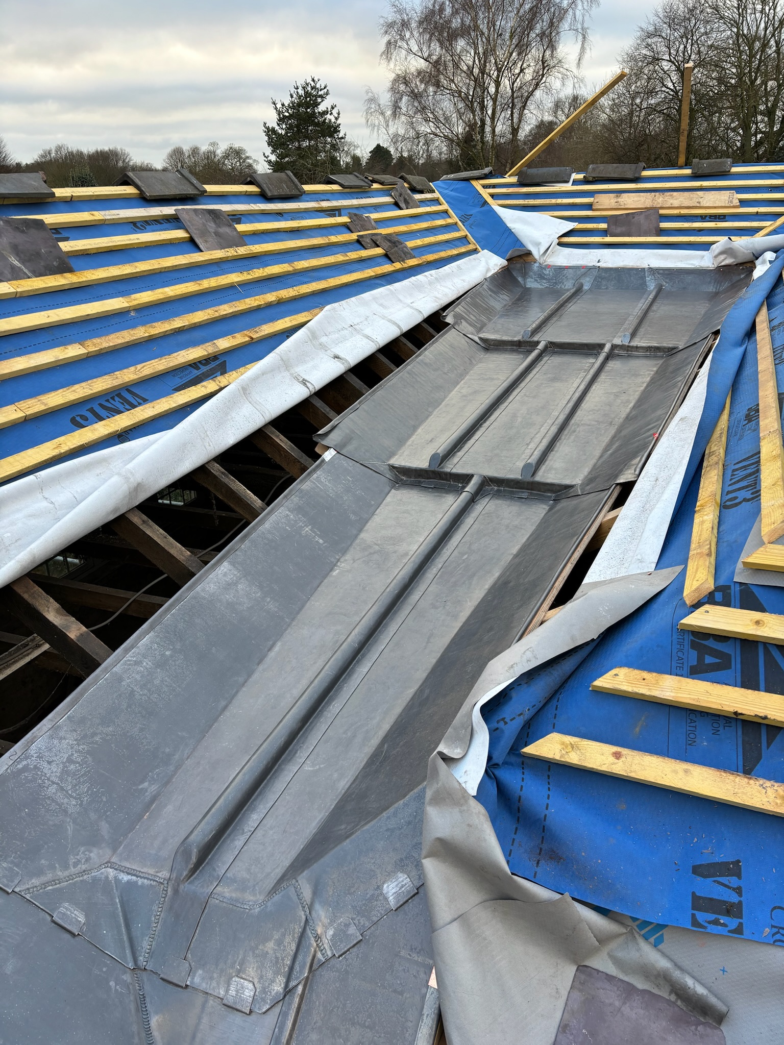
Worked Example (Code 6): How Designers Oversize Bays
Code 6 is a common specification choice, but it is regularly oversized in drawings. The standard maximum bay size for Code 6 on flat roofs is:
- Max width between rolls: 675mm
- Max length between drips: 2250mm
Where designers reduce bay length to around 1800mm, bay width may sometimes be increased to around 840mm to maintain a similar bay area. However, this should be treated as an exception requiring justification and low exposure conditions. If the roof is exposed, high-solar, or subject to foot traffic, remain within standard limits for correct lead bay sizes.
CPD Note: Bay Geometry as a Primary Design Control
Correct bay sizing must be embedded in design information. It should be defined on drawings and schedules, not delegated to a contractor as an aesthetic decision. Bay geometry should be coordinated with:
- roof falls and drainage strategy (including overflow routes)
- structure and deck layout
- upstands, abutments and penetrations
- insulation sequencing and ventilation strategy beneath lead
- maintenance access routes and foot traffic control
Any tender that proposes larger bays than the guidance should be treated as a technical risk and rejected unless the design has been formally reworked.
Specify Correct Lead Bay Sizes (Design-Led Compliance)
Start with correct lead bay sizes, then choose the correct lead code and detail joints to allow controlled thermal movement.
Use the Lead Code SelectorShop Rolled Lead Sheet
Checklist: Correct Lead Bay Sizes (Quick Spec Review)
- Confirm roof pitch category (≤10°, 11°–60°, or 60°–80°).
- Set bay length in the direction of fall using drips or laps.
- Set bay width across the fall using rolls or mechanical joints.
- Ensure both dimensions comply with Code 4–8 limits.
- Reduce bay sizes in exposure, solar loading, or foot traffic zones.
- Detail perimeters and junctions to avoid restraint.
- Coordinate ventilation strategy beneath lead where required.
FAQ: Correct Lead Bay Sizes (Architect & Specifier Questions)
What are “correct lead bay sizes”?
Correct lead bay sizes are the maximum permitted lead sheet dimensions (width and length) for each lead code, set to control thermal movement and prevent fatigue cracking. Both bay width and bay length must comply.
Does using thicker lead allow larger bays?
Thicker lead allows some increase in bay size, but it does not remove movement. Oversized bays will still fail. Correct lead bay sizes must be followed regardless of thickness.
What controls bay length on flat roofs?
Bay length (direction of fall) is controlled by drips. The maximum distance between drips depends on lead code.
What controls bay length on pitched roofs?
On pitched roofs, bay length is controlled by laps. The maximum distance between laps depends on lead code and pitch range.
What controls bay width?
Bay width (across the fall) is controlled by rolls or mechanical joints. Exceeding width limits increases uplift and deformation risk.
Can I reduce bay length and increase bay width?
Only in limited circumstances, with justification, low exposure and correct detailing. In most professional specifications, it is safer to remain within standard limits for correct lead bay sizes.
Why do lead roofs crack years after completion?
Fatigue cracking typically results from repeated thermal cycling where bays are oversized or restrained. Ensuring correct lead bay sizes and restraint-free detailing is the most reliable prevention strategy.
Conclusion: Correct Lead Bay Sizes Are a Design Requirement
Correct lead bay sizes are not optional guidance. They are a design requirement for durable performance. Whether you are detailing a flat roof, pitched roof, dormer top, canopy or parapet gutter, the route to long service life is the same: compliant bay geometry, correct jointing, and detailing that allows controlled thermal movement.
If you want a visual reference for joint formation and movement detailing, use the Lead Lads YouTube channel. For competent delivery and specialist coordination on high-risk roofs, see Neal Roofing leadwork and The Lead Lads, and review the workmanship baseline at Leadwork Standards.