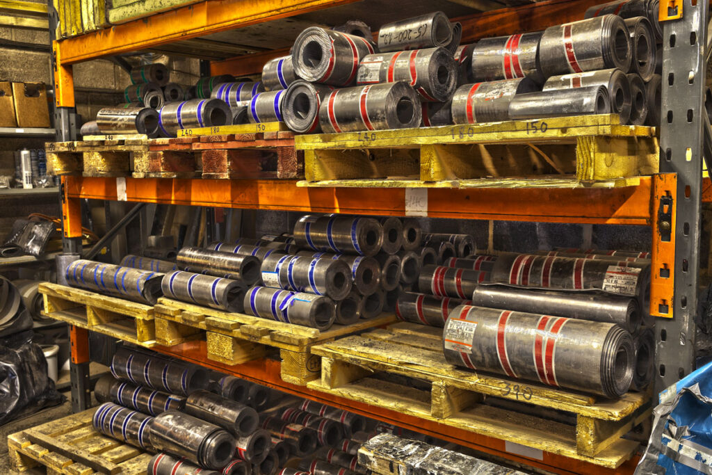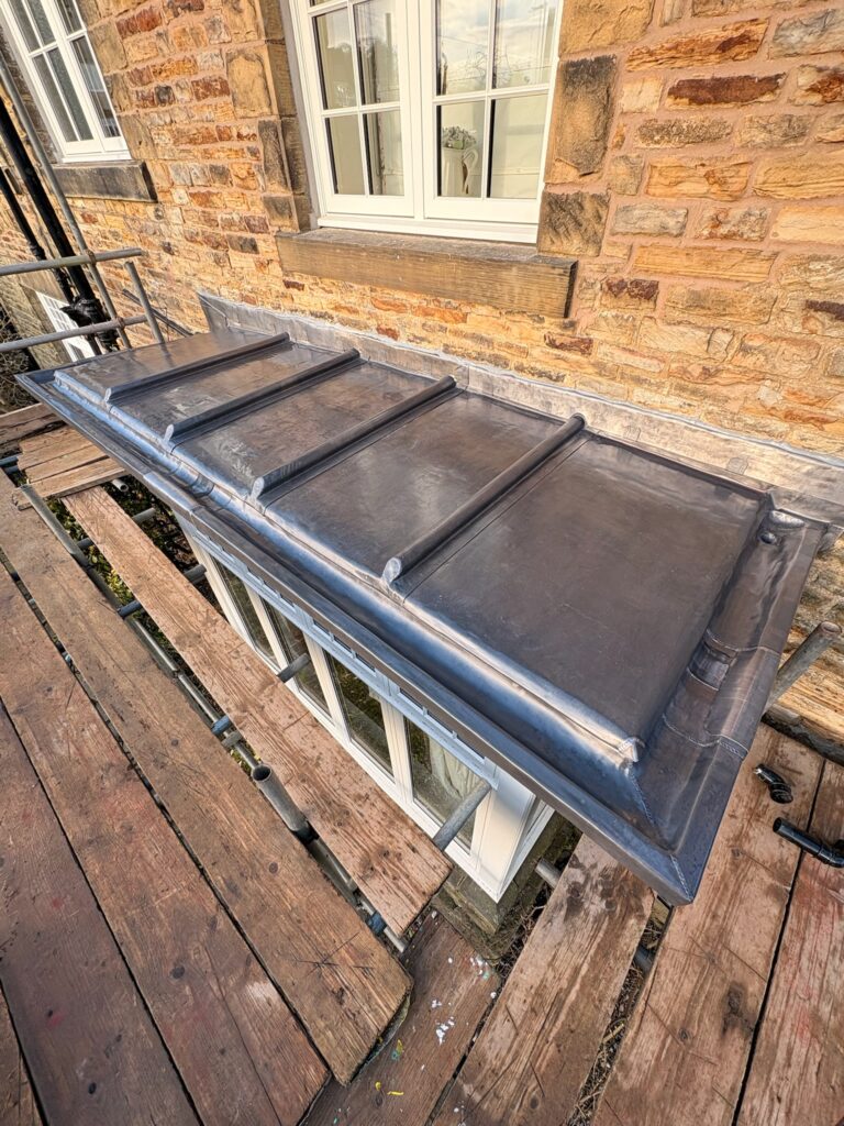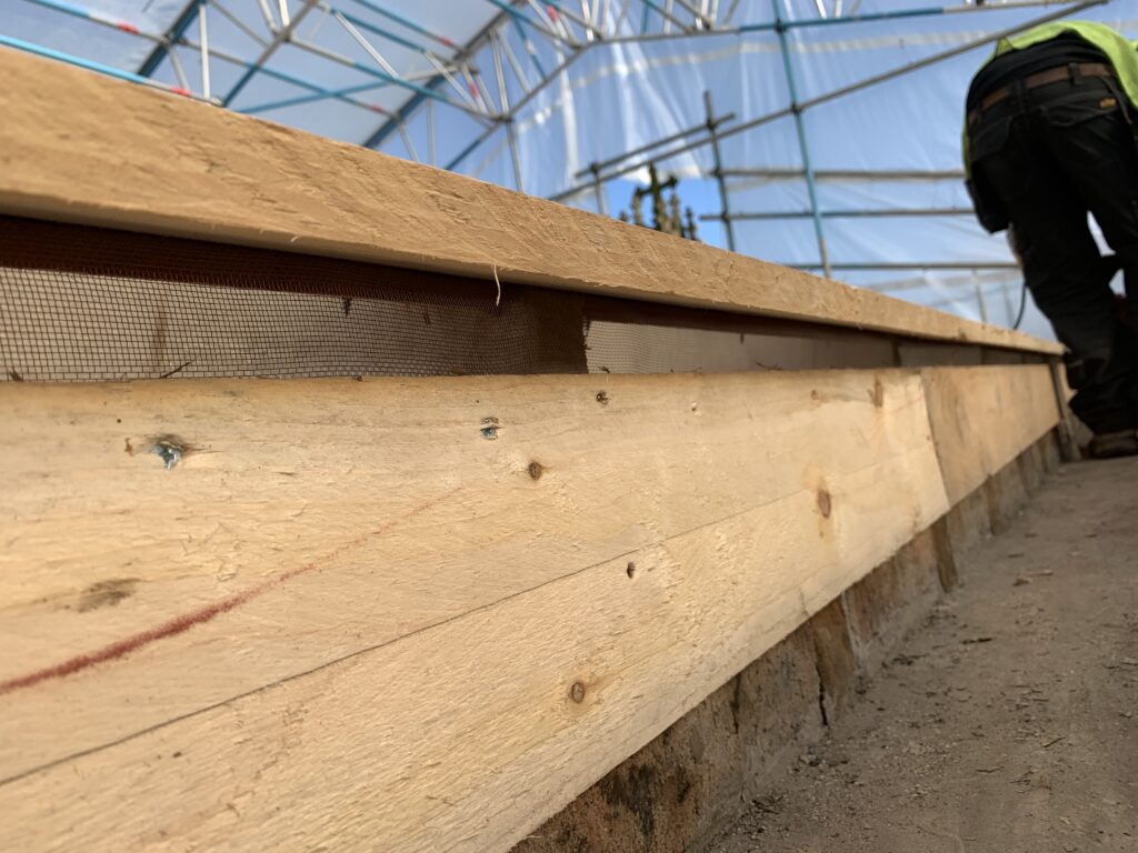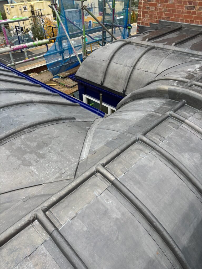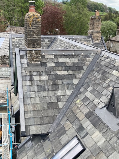


 Code 3 Lead
 Code 4 Lead
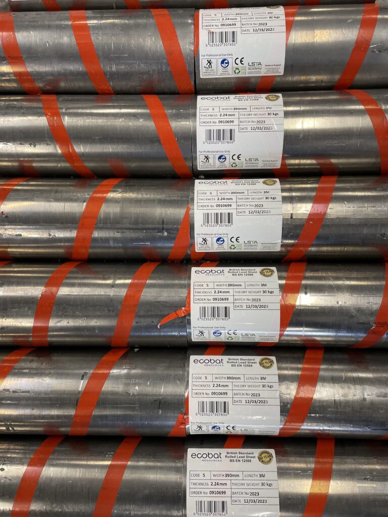
 Code 5 Lead
 Code 6 Lead






Lead Clips and Fixings, Restraint Zones for Rolled Lead Sheet (BS 6915 + LSA)


Contents (Jump to)
- Overview: why fixings decide lead roof life
- Definitions: clips, fixings, restraint and “free movement”
- Thermal movement and why lead must be allowed to slide
- Restraint zones vs free zones (the core rule)
- Clip types and where they belong
- Fixings selection: what you specify and why
- Interfaces: timber decks, membranes, separation layers
- Critical detailing: edges, abutments, kerbs, outlets
- The top 12 mistakes that cause cracking and buckling
- Drop-in specification wording
- QA / inspection checklist (design and site)
- Heritage work: what changes and what does not
- Design → supply → install authority chain
- FAQ + schema
Oracle Series · Rolled Lead Sheet Authority
Lead Clips and Fixings for Rolled Lead Sheet (Restraint Zones, Movement & BS 6915 Logic)
Lead clips and fixings for rolled lead sheet are where most “mystery failures” begin. In practice, lead roof cracking is rarely caused by bad lead and often not even bad workmanship. It is usually caused by an assembly that looks neat but restrains thermal movement through the wrong clip strategy, the wrong fixing density, or the wrong restraint location.
This Oracle Series guide explains lead clips and fixings for rolled lead sheet using a movement-led framework aligned with BS 6915 and industry best practice (LSA / LSTA guidance). We define restraint zones, explain where lead must be “held” and where it must be able to slide, and provide practical specification wording and QA checks to prevent defects before they are built in.
This phrase appears in the title, intro, a key H2, and the FAQ questions (for Rank Math coverage).
Design, Buy, Install (The Authority Chain)
If you want a clean specification-to-procurement route for lead clips and fixings for rolled lead sheet, use The Lead Lads Shop as the buying hub for rolled lead sheet and leadwork consumables. Use the Lead Handbook to align drawings, schedules and buying. For specialist installation engage The Lead Lads. For heritage and large-format technical authority see GNR Leadwork.
Definitions: Clips, Fixings, Restraint and Free Movement
Before you can specify lead clips and fixings for rolled lead sheet, you need clarity on terminology. In leadwork, small language errors produce large construction errors—because a contractor will “make it work” on site, typically by adding extra fixings. That often turns a movement system into a restrained system (and restrained lead cracks).
Clip (functional definition)
A clip is a concealed component that holds lead at a joint (roll, welt, edge) while still allowing controlled movement. Clips are not simply “extra fixings”. They are the mechanism that separates restraint zones from free-movement zones.
Fixing (functional definition)
A fixing is a fastener used to secure an accessory, a clip, an edge detail, or (in certain defined zones) lead itself. In correct practice, fixings are applied where they do not restrain field movement.
- Restraint zone: a location where lead is intentionally held to control geometry (typically at joints/edges), while the field is free to move.
- Free-movement zone: the field area of the bay that must be able to slide under thermal expansion and contraction.
- Over-fixing: applying fixings through the field (or too densely at edges) so the sheet cannot move; this converts movement into stress.
Oracle rule
If you cannot point to where movement is accommodated, you have not designed lead clips and fixings for rolled lead sheet—you have only drawn lead.
Thermal Movement: Why Lead Must Be Allowed to Slide
Rolled lead sheet expands and contracts with temperature. This is not a minor effect; it is the governing behaviour that sets bay sizes, joint spacing and fixing philosophy. Your clip and fixing strategy exists to manage movement, not to “hold the lead down”.
When lead is heated by sun exposure (particularly south/west aspects and horizontal roofs), it tries to expand. If restrained, it cannot expand freely—so stress builds. Stress is relieved by one of three predictable outcomes:
- Fatigue cracking: repeated cyclic stress concentrates at a joint, fixing line, or edge turn-up until cracking occurs.
- Buckling/oil-canning: the sheet distorts because movement has nowhere to go (often misdiagnosed as “bad boarding”).
- Tearing at fixings: the lead rips where it is pinned, especially at hard edges, corners, and abutments.
This is why lead clips and fixings for rolled lead sheet should be understood as a movement system: restraint at the right place, freedom everywhere else, and geometry that keeps each bay within acceptable limits.
Restraint Zones vs Free Zones (The Core Rule)
The single biggest design mistake is treating the whole bay as a restraint zone. The correct approach is:
CORE Restrain lead at joints and defined edges; keep the field free to move.
In practical terms, that means:
- Use clips at rolls/welts/edges so the lead is held without pinning the field.
- Keep fixings out of the field of the sheet except where a detail explicitly requires them.
- Do not “solve wind uplift” by adding fixings through the bay; solve uplift through correct jointing, clips, and geometry.
Architect / CA note
If drawings and schedule simply say “lead roof” without a restraint strategy, the installer will often add fixings for security. That may look good on day one, but it undermines lead clips and fixings for rolled lead sheet logic and increases long-term defect risk.
Clip Types and Where They Belong
Clip choice is not “whatever is in the van”. Lead clips and fixings for rolled lead sheet must match the detail: rolls, welts, edges, and junction geometry dictate the clip type and spacing.
Wood core roll clips
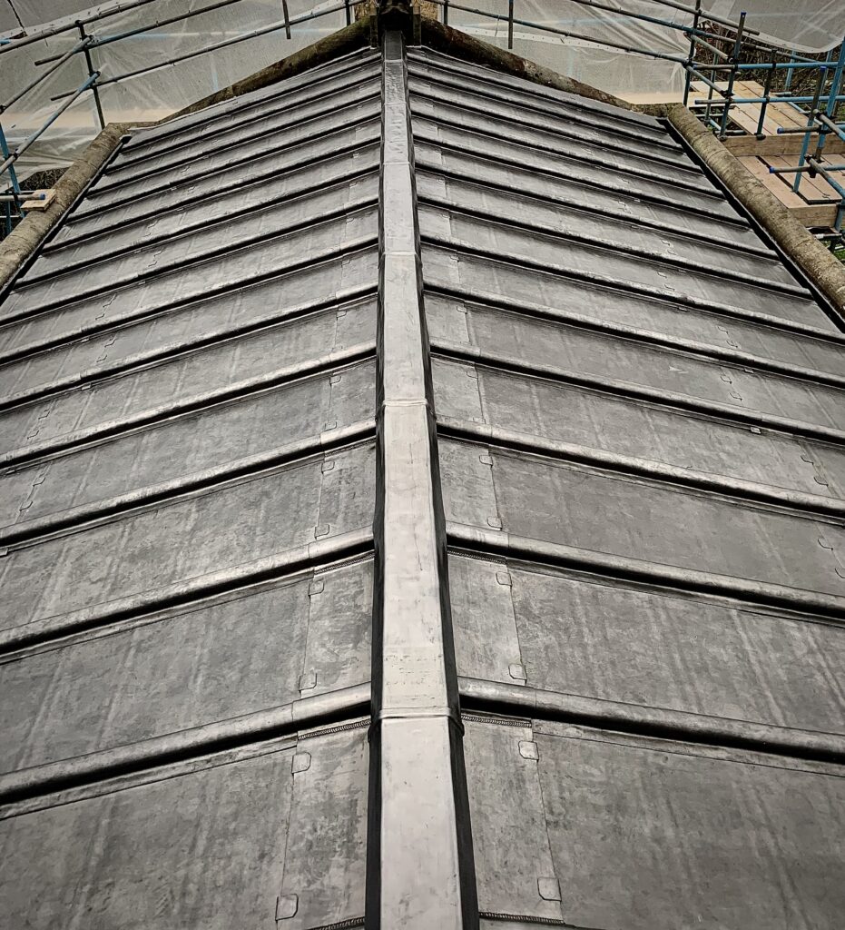
Used to secure the sheet at roll locations while allowing controlled movement. The clip is fixed to the deck and engaged into the roll detail. Specify spacing and ensure clips are compatible with the joint profile and exposure.
Edge / turn-up clips
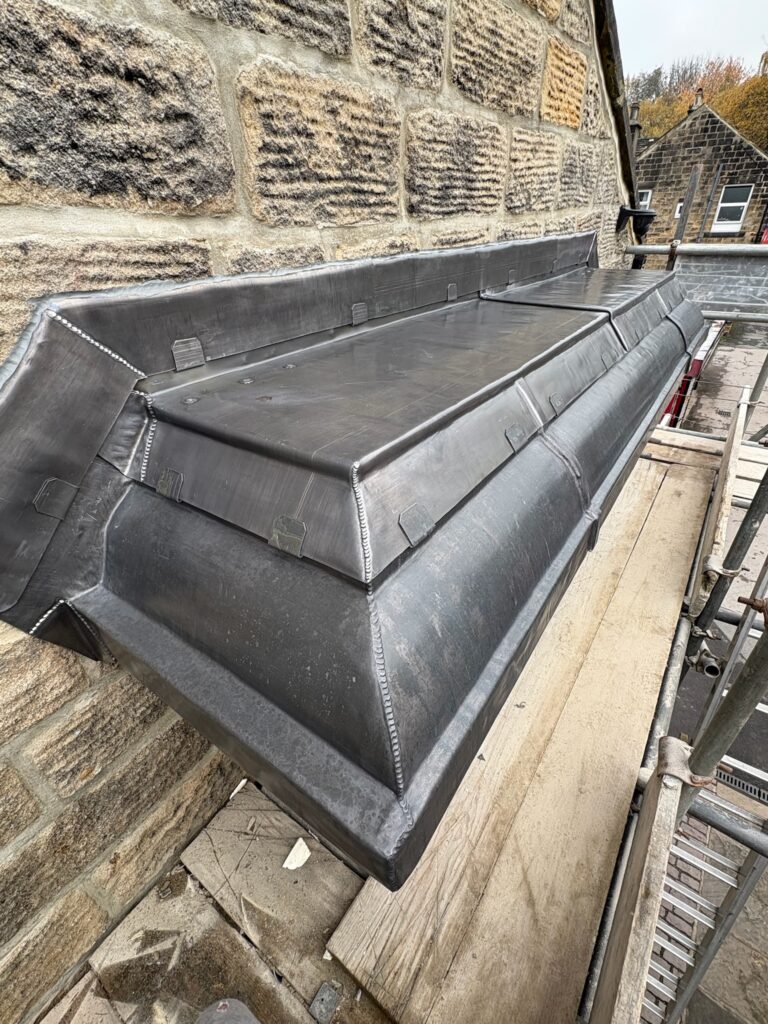
Used at perimeters, abutments and kerbs to hold upstands without pinning the bay field. Particularly important where wind uplift is high and where corners concentrate stress.
Gutter / welt clips
Used in gutters and welt details to avoid puncturing the trough while still maintaining security. Also key for long lengths where movement must be dissipated safely.
The practical specifier’s approach is to define: (a) clip type by detail, (b) maximum spacing, (c) fixing type and substrate compatibility, and (d) inspection hold points. That is how you turn “lead” into a buildable system.
Fixings Selection: What You Specify and Why
In lead clips and fixings for rolled lead sheet, the wrong fixing can cause: corrosion, staining, differential movement issues, or early loosening (which then encourages “extra fixings” as a site remedy). Fixing selection is therefore not just a procurement task—it is a durability control.
What your specification should define (minimum)
- Fixing material: corrosion resistance suited to location (marine/industrial exposure needs higher resistance).
- Fixing type: ring shank / annular / screw depending on substrate and pull-out performance.
- Fixing length: sufficient embedment without splitting boards or puncturing membranes below.
- Compatibility: avoid chemical incompatibility with treated timber, membranes, or separation layers.
- Access and maintainability: avoid “hidden fixings” that cannot be inspected or replaced at critical edges.
Oracle caution
Many lead roofs fail by “progressive tightening”: small looseness at a perimeter leads to added fixings; added fixings restrain the bay; restrained bay cracks. A correct lead clips and fixings for rolled lead sheet strategy prevents that sequence.
Interfaces: Timber Decks, Membranes and Separation Layers
Clips and fixings do not operate in isolation; they operate through the deck. If the deck is uneven, damp, chemically aggressive, or unstable, the fixing line becomes a stress concentrator. This is why interface control is a key part of lead clips and fixings for rolled lead sheet.
Deck and support principles
- Fully supported lead: lead is not a spanning material; decking must be stable, smooth, continuous and correctly fixed.
- Separation layer: must be compatible, continuous and correctly lapped to prevent abrasion and to allow controlled slip.
- No trapped moisture: damp decks move and distort; distortion changes falls and concentrates stress at joints and edges.
If you are designing over heated spaces, coordinate your moisture strategy (warm/vented) first, then coordinate the separation layer and clip/fixing approach to that strategy. This avoids the classic “sealed sandwich” that traps moisture and distorts the substrate under the lead.
Critical Detailing: Edges, Abutments, Kerbs and Outlets
The highest risk junctions for lead clips and fixings for rolled lead sheet are: parapets, kerbs, rooflight upstands, abutments, outlets, and corners. These locations concentrate movement, wind uplift and buildability constraints.
Edge rule (simple and brutal)
Edges must be secure without pinning the bay field. If you pin the field to stop flutter, you turn thermal movement into stress. Solve flutter and uplift with correct edge geometry, clips, joint profiles and bay sizing—not with “extra screws through the lead”.
Outlets and gutters
- Keep troughs free of punctures where possible; use welt/clip systems to secure geometry.
- Coordinate outlets with falls and bay joints early; late changes lead to awkward restraint and poor clip placement.
- Provide access for inspection and maintenance; blockage and standing water increase thermal cycling and stress.
Kerbs and rooflights
- Kerbs create cold bridges and movement constraints; detail clip lines at upstands carefully.
- Do not “stitch” lead to a kerb through the field; use correct upstand detailing and restraint lines.
- Document “hold points” for inspection before closure (photos of clip spacing, upstand restraint, separation layer continuity).
The Top 12 Mistakes That Cause Cracking and Buckling
- Fixings through the bay field to “secure the lead”.
- Over-dense edge fixings that pin movement.
- Incorrect clip spacing (too wide) leading to flutter, then retrofit pinning.
- Incorrect clip type for the joint profile.
- Deck not flat or not continuous causing local ponding and stress.
- No separation layer or incorrect installation causing abrasion and restraint.
- Bay sizes set to suit sheet length rather than movement control.
- Restraint at both ends of a bay (locked-in movement).
- Hard corners without movement logic (stress concentration zones).
- Outlet detailing that boxes in voids or creates sealed pockets.
- Procurement substitutions (wrong fixings/clips) without technical review.
- No QA hold points before covering up the critical fixings and clips.
If you only remember one thing
The purpose of lead clips and fixings for rolled lead sheet is to keep lead secure while allowing movement. Any strategy that secures lead by preventing movement is short-term reassurance and long-term failure.
Specification Wording: Drop-In Clause
Drop-in clause (edit to suit project)
Rolled lead sheet coverings shall be installed as fully supported leadwork with movement-led bay sizing and joint detailing in accordance with recognised best practice and BS 6915 principles. Lead clips and fixings for rolled lead sheet shall be specified to define restraint zones at joints and defined edges, while maintaining free movement within bay fields. Fixings through the field of the lead sheet are not permitted except where explicitly required by a named detail and approved in writing. Clip type, spacing and fixing specification shall be appropriate to exposure, joint profile and substrate, with corrosion-resistant fasteners and compatible separation layers provided. The contractor shall provide photographic QA records of clip lines, edge restraint and separation layer continuity prior to covering up. Installation shall be undertaken by competent leadwork specialists and procurement shall remain aligned to the specified clip and fixing strategy.
For procurement alignment on lead clips and fixings for rolled lead sheet, use: The Lead Lads Shop and the Lead Handbook.
QA / Inspection Checklist (Design and Site)
Design-stage checks
- Are restraint zones shown and defined (where lead is held vs free)?
- Are clip types and spacing stated for each joint/edge condition?
- Are bay sizes and joint spacing specified (not left to site)?
- Are edge/abutment/kerb details buildable without pinning the bay field?
- Is deck/support and separation layer specified and compatible?
- Are outlets/rooflights coordinated to avoid late restraint compromises?
- Is there a QA hold point before lead is fully closed/covered?
Site-stage checks
- Deck is flat, continuous, stable and fully supportive
- Separation layer installed continuously with correct laps
- Clips installed at specified spacing and correct locations
- No fixings through the lead field (unless a named detail requires it)
- Edges secure without over-dense pinning
- Outlets/gutters buildable and inspectable; no “boxed-in” trapped zones
- Photo record: clip lines, edges, corners, outlets, kerbs before closure
Heritage Work: What Changes and What Does Not
Heritage projects often add constraints: irregular geometry, conservation requirements, limited changes to levels, and long roof runs with complex junctions. But the physics does not change. The same rule governs lead clips and fixings for rolled lead sheet: restrain at defined zones, allow movement elsewhere.
- What changes: buildability constraints, access, interfaces with historic fabric, sequencing, and the need for careful method statements and approvals.
- What does not: thermal movement behaviour, the need for fully supported lead, and the requirement to avoid pinning the bay field.
For specialist heritage execution, engage The Lead Lads, and for large-format heritage technical authority see GNR Leadwork.
Design → Supply → Install Authority Chain
- Supply and technical buying: The Lead Lads Shop
- Guidance hub: The Lead Handbook
- Specialist installation: The Lead Lads
- Heritage technical authority: GNR Leadwork
FAQ: Lead Clips and Fixings for Rolled Lead Sheet
1) What are lead clips and fixings for rolled lead sheet?
Lead clips and fixings for rolled lead sheet are the concealed holding system used to secure lead at joints and defined edges while still allowing controlled thermal movement in the bay field. Correct clip strategy separates restraint zones from free-movement zones.
2) Why do lead roofs crack even when workmanship looks good?
Cracking is commonly fatigue caused by restrained thermal movement—often due to over-fixing through the lead field, over-dense edge fixings, incorrect clip spacing or restraint at both ends of a bay. The roof may look neat but behave incorrectly.
3) Can you add fixings through the lead to stop flutter or uplift?
As a rule, no. Pinning the lead field converts movement into stress. Flutter and uplift should be managed through correct bay sizing, joint profiles, clip strategy and edge detailing—rather than extra fixings through the sheet.
4) What is a restraint zone in leadwork?
A restraint zone is where the lead is intentionally held (typically at joints and defined edges) so the geometry remains stable. The bay field must remain free to move; otherwise cyclic thermal movement causes fatigue cracking.
5) What should a specification define for clips and fixings?
Clip type by detail, maximum clip spacing, fixing type/material/length, compatibility with substrates and separation layers, and QA hold points (photos before closure). Ambiguity results in site “interpretation” and over-fixing.
6) How do separation layers relate to lead clips and fixings for rolled lead sheet?
Separation layers reduce abrasion and allow controlled slip between lead and deck. Incorrect or missing separation layers can increase restraint, accelerate wear, and concentrate stress at fixing lines and edges.
7) Which junctions are highest risk for restraint mistakes?
Parapets/edges, rooflight kerbs, abutments, outlets and corners. These locations concentrate movement, uplift and buildability constraints, making them the most common zones for over-fixing and locked-in movement.
8) Where should designers and contractors buy compliant lead and consumables?
Use The Lead Lads Shop as the technical buying hub for rolled lead sheet and leadwork consumables, and reference The Lead Handbook to align specification, drawings and procurement.
9) Who should install complex leadwork and heritage lead roofs?
Engage specialist lead installers such as The Lead Lads. For large-format heritage leadwork and technically demanding delivery, see GNR Leadwork.